566 Voltage Controlled Oscillator(VCO) Calculator
The LM566/NE566/SE566 is a general purpose voltage controlled oscillator(VCO) that provides simultaneous square and triangle wave output as a function of the input voltage. It is used in frequency modulation circuit(FM circuits), PM circuits, used as signal generator, function generator, clock generator, in Phase Locked Loop(PLL) circuits.
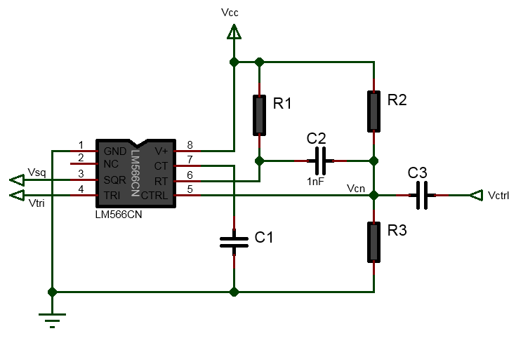
The above 566 Voltage Controlled Oscillator(VCO) calculator calculates the DC control voltage(Vcn) at the pin 5 formed by the voltage divider R2 and R3 on which the applied external modulating signal(Vctrl) is superimposed. This voltage is taken as the mean of 3/4Vcc and Vcc, that is Vcn = (3/4Vcc+Vcc)/2. It also calculates the resistor values R1 and R2 from the given power supply voltage Vcc, desired frequency fo and the R3 resistor value. The following are the equation used for calculating these values:
\(Vcn = \frac{3/4V_{cc}+V_{cc}}{2}\)
\(R_1 = \frac{2.4(V_{cc}-V_{cn})}{fC_1V_{cc}}\)
\(R_2 = \frac{R_3(V_{cc}-V_{cn})}{V_{cn}}\)
Notes:
- the resistor value R1 should be in the range:2KΩ < R1 < 20KΩ
- the typical amplitude of the square wave is about 5.4Vpp
- the typical amplitude of the triangle wave is about 2.4Vpp
- Max frequency is 1MHz
- 10:1 frequency range with fixed capacitor
See the tutorial How LM566/NE566 Voltage Controlled Oscillator(VCO) Works where the operation of VCO is explained in details with example calculation.
