
About LC Parallel Resonant Circuit Calculator
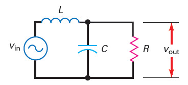
The above online calculator for second order LC low pass filter calculates the cutoff frequency and Q from given inductor, capacitor and load resistor values or calculate inductor, capacitor values from given cutoff frequency.
Notes on Second Order LC Low Pass Filter Calculator
The Q of the filter is given by,\[Q=\frac{R}{X_L}\]where, the inductor reactance \(X_L\) is calculated at the resonant frequency. When Q is high the gain will increase and in frequency response graph we will see peak. The following graph illustrates frequency response of LPF when Q is high.


The quality factor Q of the LC parallel tank is given by the following equation:
\(Q=\frac{Energy \space stored \space in \space Reactive \space component}{Energy \space dissipated}\)
or, \(Q=\frac{X_C}{R_w}=\frac{X_L}{R_w}\)
Some example usage of this online LC parallel resonant circuit calculator are as follows.
- How does Single Diode Modulator Circuit work?- Simple Amplitude Modulation (AM) circuit using Single Diode Modulator
