Clear Timer on Compare (CTC) mode is a mode of operation for the timers in microcontrollers. It is used to generate a specific frequency of square wave signals by comparing the timer's counter value to a predetermined value, also known as the compare value.
In this Timer tutorial, some examples with program code of using ATmega328p CTC mode are provided and the difference of the normal mode and the CTC mode of a timer is explained.
Timers and CTC pins
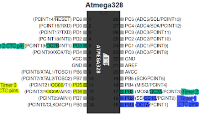
The ATmega328P has 3 timers/counters called Timer 0, Timer 1 and Timer 2. The Timer 0 and Timer 2 are 8 bits timers while the Timer 1 is 16 bit timers. Each of these Timer of equipped with Clear Timer on Compare Match(CTC) feature. Each timer has two compare units and hence each timer can generate CTC signal on two pins. The Timer 0 generates CTC signal on pin PD6(OC0A) and PD5(OC0B), the Timer 1 generates CTC signal on pin PB1(OC1A) and PB2(OC1B) and the Timer 2 generates CTC signal on pin PB3(OC2A) and PD3(OC2B). This is shown in the picture below.

Timer 0
In this tutorial we will use the Timer 0.
There are two advantages of CTC mode of the timer. First, CTC mode provides users for greater and flexible control of frequency of the output square wave signal generated at the OC0A or OC0B pins. The second advantage of CTC mode is that this mode simplifies the counting of external events.
When using Timer 0 CTC mode, we load count value(also called compare value) into either the OCR0A or OCR0B register. Once loaded we can start the timer and the timer will count from 0 to the value loaded into the OCR0A(or OCR0B) register. Once the count value is reached, match occurs and the OCF0A flag(or OCF0B flag) in the TIFR0 register is set. We can then either poll, that is, monitor this OCF0A flag (or OCF0B flag) and take necessary further action such as turning on LED or switch, generate waveform, sample or output data etc. Or we can setup interrupt that triggers the ISR(TIMER0_COMPA_vect) or ISR(TIMER0_COMPB_vect) function automatically whenever a match occurs. In the ISR() function we can write program code to do our task such as turning on LED or switch, generate waveform, sample or output data etc.
The formula to calculate value of count to be loaded in OCR0A register(or OCR0B register) is as below.
\[C=\frac{F_{clk}}{2 N F_{w}}-1\]
where, Fclk is the microcontroller CPU clock frequency, N is the pre-scalar value and Fw is the output wave frequency.
The above equation can be rewritten in the following form where we use the output square wave time period(Tw) instead of the frequency(Fw).
\[C=\frac{F_{clk} T_{w}}{2 N}-1\]
For example, if we want to create square wave signal with time period of Tw=100us, that is frequency of 10KHz, with CPU frequency of 8MHz and using pre-scalar of 8 we can calculate the count value to be loaded into the OCR0A as follows,
\[C=\frac{8*10^6*100*10^{-6}}{2*8}-1\]
we get,
C = 49
Important Registers for CTC mode
The important registers for configuring the ATmega328p microcontroller in CTC mode are as follows.
a. TCCR0A – Timer/Counter 0 Control Register A


The function of the Compare Output Modes bits COM0B1, COM0B0 in Phase Correct PWM mode is as follows.

b. TCCR0B – Timer/Counter 0 Control Register B


c. TIMSK0 – Timer/Counter 0 Interrupt Mask Register

d. TIFR0 – Timer/Counter 0 Interrupt Flag Register

e. OCR0A – Output Compare Register0 A

f. OCR0B – Output Compare Register0 B

Programming Examples of ATmega328p in CTC mode
We can use CTC mode with polling method and in interrupt method. First we illustrate how to write code in CTC mode with polling method. Then we show how to write code for interrupt with CTC mode. In both examples we will use the OCR0A register.
CTC mode with Polling
Following is C program code that configures Timer 0 in CTC mode in toggle mode with prescalar of 8. This then will generates square wave at the OC0A pin(Port D Pin 6) at the frequency determined using the formula above. Here we have setup to generate square wave of 10KHz which is equivalent to time period of 100us. Note that in order to output signal at the OC0A pin it must be configured as output using the DDRD register for that pin 6.
# C program code
#ifndef F_CPU
#define F_CPU 8000000UL
#endif

#include <avr/io.h>

void ctcDelay();


int main()
 {
   DDRD |= (1<<PD6);    //make PORT D pin 6(OC0A pin) an output pin

   while (1){
		ctcDelay();
	}

   return 0;
 }


ctcDelay(){
	OCR0A = 49;	//load 49 into OCR0A for delay of 100us
	//configure timer0 for CTC mode with prescalar of 8
	TCCR0A |= (1<<COM0A0) | (1<<WGM01);
	TCCR0B |= (1<<CS01);

	while((TIFR0 &  (1<<OCF0A)) == 0);	//check OCF0A flag
	TIFR0 = (1<<OCF0A);	//clear OCF0A flag
}
Alternatively we can also use the same code to generate square wave at other pin other than the OC0A pin. The following shows the schematic diagram for the above setup.
CTC mode with Interrupt
In this Programming ATmega328p in CTC mode example we will use the interrupt feature of CTC mode. In this method, we will enable the interrupt mode for the output compare match. For this we have to enable the output compare interrupt enable bit(OCIE0A) for the timer output compare match A which is located in the TIMSK0 register(see above).
#C program code for CTC mode with Interrupt
#ifndef F_CPU
#define F_CPU 8000000UL
#endif

#include <avr/io.h>
#include <avr/interrupt.h>

int main()
 {
   DDRD |= (1<<PD6);

   OCR0A = 49;	//load 49 into OCR0A for delay of 100us
	//configure timer0 for CTC mode with prescalar of 8
	TCCR0A |= (1<<COM0A0) | (1<<WGM01);
	TCCR0B |= (1<<CS01);
	TIMSK0 |= (1<<OCIE0A);	//enable  timer0 output compare match A interrupt
	sei(); 	//set global interrupt

   while (1);

   return 0;
 }

ISR(TIMER0_COMPA_vect){

}
In the above code for Timer/Counter Interrupt using CTC mode, we have configured the microcontroller to generate 10KHz square wave signal at the OC0A pin. The CPU clock frequency is 8MHz and pre-scalar of 8 was used. So to generate 10KHz signal(time period of 100us) we have loaded the OCR0A register with count value of 49. This was calculated above. You can also use the ATmega32A Timer Calculator which gives the same value of count for ATmega328p microcontroller. In order to use the interrupt we have to include the interrupt.h header file and also make the OC0A pin an output pin using the DDRD register. The TCCR0A and TCCR0B registers bits are configured so that the CTC mode is selected with toggle mode for the OC0A pin. Then we have to enable the interrupt by setting the OCIE0A bit in the TIMSK0 register. Afterwards we have to enable the global interrupt bit I in SREG register using the sei() function.
Conclusion
Programming the ATmega328P in CTC mode is a useful technique for generating precise square wave signals. By following the steps outlined in this blog post, you should be able to program the ATmega328P in CTC mode and create your own electronics projects that require precise timing. In this Programming ATmega328p in CTC mode tutorial we showed how to configure the micrcontroller in CTC mode and how to use the polling and interrupt method.